디지털 시스템 설계 및 실험 - Decorder, Encoder, Multiplexer


디지털 시스템 설계 및 실험 - Decorder, Encoder, Multiplexer

디지털 시스템 설계 및 실험 결과보고서
실험제목
Decorder, Encoder, Multiplexer
실험목표
Decoder : 2-to-4 line decoder 구현
2-to-4 line decoder를 이용하여 3-to-8 구현
3-to-8 2개 이용하여 4-to-16 구현
(시뮬레이션에선 4-to-16을, COMBO에서는 3-to-8을 할 예정)
Encoder : 16-to-4 encoder 구현
Multiplexer : 2-to-1 MUX 구현
2-to-1 MUX 3개 이용하여 4-to-1 MUX 구현
4-to-1 MUX 4개 이용하여 16-to-4 MUX 구현
실험결과
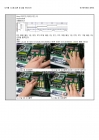
2-to-4 line decoder 구현
코딩
module ttfd(A[0],A[1],D[0],D[1],D[2],D[3]);
output [3:0]D;
input [1:0]A;
wire [1:0]NA;
not (NA[0],A[0]);
not (NA[1],A[1]);
and (D[0],NA[0],NA[1]);
and (D[1],A[0],NA[1]);
and (D[2],NA[0],A[1]);
and (D[3],A[0],A[1]);
endmodule
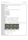
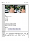
시뮬레이션
00, 01, 10, 11 일 때 각 각 D[0],D[1],D[2],D[3]이 1이 된다.
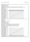
2-to-4 line decoder를 이용하여 3-to-8 구현
코딩
module tted(A[0],A[1],A[2],D[0],D[1],D[2],D[3],D[4],D[5],D[6],D[7]);
output [7:0]D;
input [2:0]A;
wire [3:0] O;
not (NA,A[2]);
ttfd t1 (A[0],A[1],O[0],O[1],O[2],O[3]); /2 to 4 line decoder
....
실험제목
Decorder, Encoder, Multiplexer
실험목표
Decoder : 2-to-4 line decoder 구현
2-to-4 line decoder를 이용하여 3-to-8 구현
3-to-8 2개 이용하여 4-to-16 구현
(시뮬레이션에선 4-to-16을, COMBO에서는 3-to-8을 할 예정)
Encoder : 16-to-4 encoder 구현
Multiplexer : 2-to-1 MUX 구현
2-to-1 MUX 3개 이용하여 4-to-1 MUX 구현
4-to-1 MUX 4개 이용하여 16-to-4 MUX 구현
실험결과
2-to-4 line decoder 구현
코딩
module ttfd(A[0],A[1],D[0],D[1],D[2],D[3]);
output [3:0]D;
input [1:0]A;
wire [1:0]NA;
not (NA[0],A[0]);
not (NA[1],A[1]);
and (D[0],NA[0],NA[1]);
and (D[1],A[0],NA[1]);
and (D[2],NA[0],A[1]);
and (D[3],A[0],A[1]);
endmodule
시뮬레이션
00, 01, 10, 11 일 때 각 각 D[0],D[1],D[2],D[3]이 1이 된다.
2-to-4 line decoder를 이용하여 3-to-8 구현
코딩
module tted(A[0],A[1],A[2],D[0],D[1],D[2],D[3],D[4],D[5],D[6],D[7]);
output [7:0]D;
input [2:0]A;
wire [3:0] O;
not (NA,A[2]);
ttfd t1 (A[0],A[1],O[0],O[1],O[2],O[3]); /2 to 4 line decoder
....

-
[기계공학 실험] DC모터 및 엔코더[ Encoder] - Matlab을 통한 PID 제어를 실습
[기계공학 실험] DC모터 및 엔코더[ Encoder] - Matlab을 통한 PID 제어를 실습 목 차 □ Encoder의 용도 □ Encoder의 외형과 구조 □ Encoder의 구조와 원리 □ Encoder 분류 □ DC 모터의 구동원리 □ DC 모터의 제어.. -
기계공학실험(엔코더)
1. Encoder의 용도 2. Encoder의 외형과 구조 3. Encoder의 구조와 원리 4. Encoder 분류 5. DC 모터의 구동원리 6. DC 모터의 제어법(PWM) 7. 실험을 하면서 느낀점 □ Encoder의 용도 - Encoder 는 회전각도, 위.. -
기계공학실험(엔코더)
□ Encoder의 용도 - Encoder 는 회전각도, 위치 이동량과 같은 아날로그 값을 디지털 값과 같이 취급할 수 있도록 코드화 전기신호로 출력하는 변환기이다. 컴퓨터 주변기기. 계측기기, 산업용 로봇, NC 공작기.. -
[논리회로실험] 멀티플렉서 디멀티플렉서
Unit 4. 멀티플렉서 디멀티플렉서 실험의 의의 Bread Board를 이용한 회로를 작성하는 것 과 기계를 만지는데 좀 더 익숙해질 수 있었다. Logic gate 의 멀티플렉서와 디멀티플렉서를 구성할 수 있다. 실험.. -
디지털 공학 BCD adder Encoder
-목차- chapter1 Contents···003 chapter2 Logic gate···005 chapter3 Simulation···006 chapter4 Picture···006 chapter5 Etc···006 1. Contents 1) BCD Adder Binary Sum BCD Sum Decimal 000100.. -
엔코더, 스텝모터 실험
실험 제목 Encoder 실험 실험 목적 회전 각도를 측정하는 증분식 Encoder의 기능 실험 실험 준비물 준비물: 증분식 엔코더 및 step motor 실험 셋 실험 방법 1. 그림과 같은 Encoder 실험 세트를 적색선을 +5V.. -
논리회로실험 - encoder decoder 7segment[7세이그먼트]
실험 목적 - Encoder, Decoder를 이해하고, 특성을 실험으로 익힌다. - 7 - segment LED decoder를 이해하고, 특성을 실험으로 익힌다. 실험 과정 1.4X2 encoder의 회로를 구현하기 위해 Quartus Ⅱ를 이용하여 인.. -
경영전략 - CJ CGV의 SWOT분석과 마케팅사례를 통한 성공요인분석과 미래제안
CJ CGV의 SWOT분석과 마케팅사례를 통한 성공요인분석과 미래제안 Ⅰ. 서론 여가란 개인이 가정, 노동 및 기타 사회적 의무로부터 자유로워진 상태 하에서 휴식, 기분전환, 자기개발 및 사회적 성취를 이루기 위.. -
마이크로프로세서 응용 및 실험 - ADC UART
마이크로프로세서 응용 및 실험 - ADC UART 1. 설계과제의 목표 및 제한조건 ◎ 제목 : 통신을 이용한 시간설정 기능이 있는 간이 시계 ●시간(0~59초)을 PC화면에 통신을 이용하여 표시 ●제한조건 - 준비물 : .. -
[컴퓨터학과] ENCODER와 DECODER
ENCODER와 DECODER 1. 실험 목적 멀티플랙서 디멀티플랙서 반가산기 전가산기의 작동원리와 구조를 이해하고, 진리표와 카르노맵을 이용해 회로를 구현할수있도록 한다. MUX 의 기능은 복수개의 입력선으로부터..